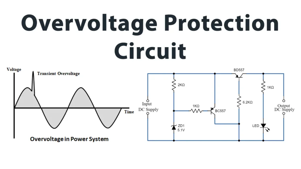
In this tutorial, we will build a Simple Overvoltage Protection Circuit designed to safeguard sensitive electronic components from voltage surges that exceed their maximum rated values. Overvoltages refer to any voltage levels that temporarily surpass the normal mains or supply voltage threshold.
Overvoltage protection (OVP) is a crucial feature in many power supplies, which instantly disconnects the power whenever the input voltage exceeds a preset limit, preventing damage to the load.
Although modern power supplies are highly reliable, failures—particularly in series regulator elements—can still occur. Manufacturers allocate significant effort to designing safety features to minimize risks.
This circuit offers a straightforward and cost-effective solution to protect devices such as microcontrollers, sensors, and other electronic modules that require stable voltage levels.
The key active components include a Zener diode, which sets the voltage limit, and two BC557 PNP transistors functioning as switches to disconnect the load when overvoltage occurs.
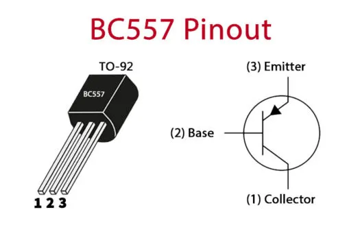
BC557 Transistor Pinout
The BC557 transistor is a PNP bipolar junction transistor with three terminals:
Emitte
Base
Collector
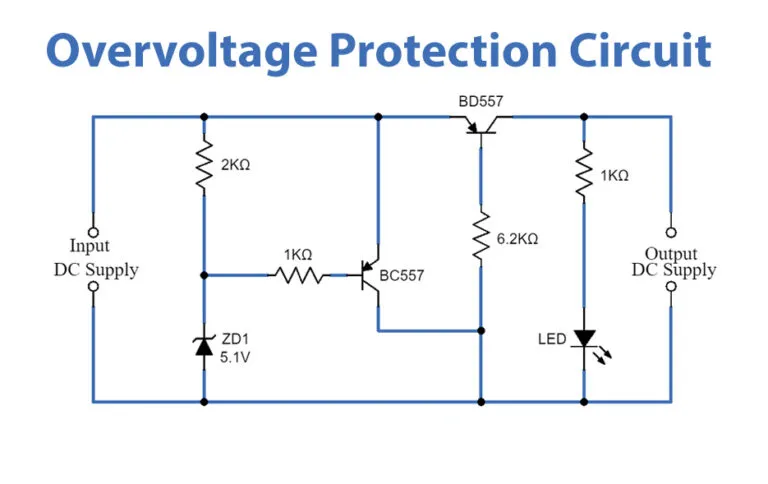
Overvoltage Protection Circuit
Working Principle
This circuit leverages the voltage regulation property of the Zener diode and the switching characteristics of two PNP transistors configured as a control switch.
Normal Operation (Voltage Below Threshold):When the input voltage is lower than the Zener diode breakdown voltage (e.g., below 5.1V for the selected diode), the diode remains reverse-biased and does not conduct. The first transistor (Q1) has its base terminal at a higher potential, meaning it is OFF (non-conductive) since it’s a PNP type. Consequently, the second transistor (Q2) has its base terminal at a lower potential, so Q2 turns ON, allowing current to flow freely from the supply to the load.
Overvoltage Condition (Voltage Exceeds Threshold):Once the voltage exceeds the preset limit, the Zener diode starts to conduct, creating a path to ground from the base of Q1, turning it ON.When Q1 is ON, its collector voltage rises, driving the base of Q2 to a higher voltage. Since Q2 is a PNP transistor, a higher base voltage means it turns OFF, acting like an open switch. This action immediately cuts off current flow to the load, thereby protecting the sensitive circuitry from the high voltage.
LED Indicator:An LED placed near the output acts as a status indicator. It lights up only when the output voltage is within the safe operating range, providing a clear visual cue of the circuit’s condition.
This design supports loads with voltages ranging from about 3.3V to 25V, covering a wide variety of low-voltage electronic devices.
Applications
This Simple Overvoltage Protection Circuit is widely used for:
Household Appliances: Protects devices like coffee makers, food processors, and washing machines from voltage surges that can damage motors or control circuits.
Consumer Electronics: Safeguards TVs, set-top boxes, and audio devices against overvoltage, preventing component failure.
Network Devices: Ensures routers, modems, and switches operate safely by blocking excessive voltage.
Computers and Digital Devices: Guards CPUs, memory, and peripherals from voltage spikes, improving system stability.
This circuit is practical, low-cost, and effective for devices operating within 3.3V to 25V voltage range.
Summary
This circuit offers an efficient and economical way to guard voltage-sensitive electronics against unexpected voltage surges. Its straightforward design with common components makes it accessible for hobbyists and professionals alike. By selecting an appropriate Zener diode voltage rating, it can be tailored to safeguard different devices and voltage levels.
For loads requiring higher current handling capability, more robust transistor alternatives can be used, or an integrated protection solution may be considered for enhanced performance.
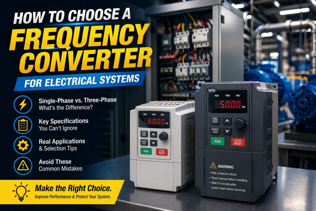
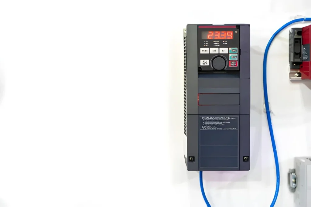
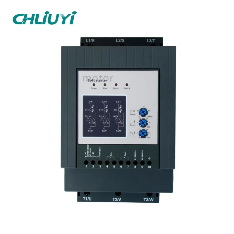
A frequency converter is often selected too late in an electrical project—after the motor, control cabinet, pump, fan, or test equipment has already been specified. That can create problems: wrong phase configuration, unstable motor operation, overheating, nuisance tripping, or a system that cannot reach the required speed or frequency condition. In an electrical system, a […]
This guide explains what a frequency converter is, its working principle, types, and differences from VFD. It covers 60Hz to 50Hz conversion scenarios, key selection factors, and common mistakes to help you choose the right device.
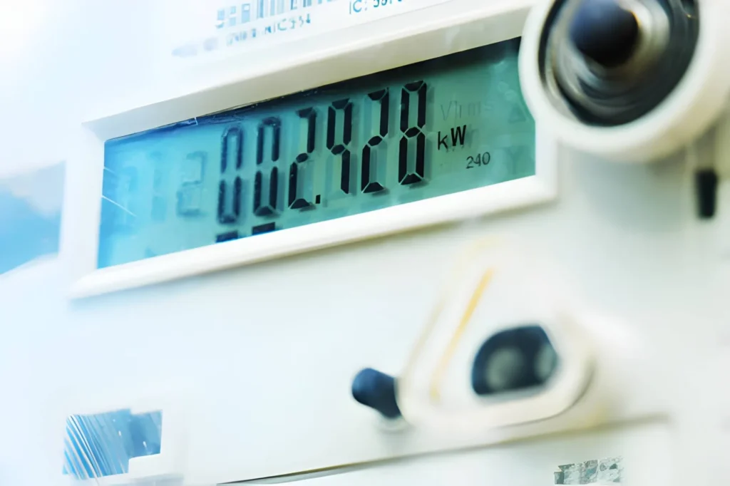
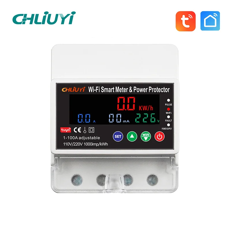
Have you ever wondered where your electricity budget really goes each month—and how electric power meters can finally give you a clear answer? Electric power meters have become essential tools for factories, commercial buildings, and smart homes that want accurate energy data instead of rough estimates and surprises on the bill. In this blog, we […]
We use cookies to enhance your browsing experience, serve personalised ads or content, and analyse our traffic. By clicking "Accept All", you consent to our use of cookies.