Modern factory power distribution systems increasingly rely on installing three-phase rail smart meters to achieve comprehensive energy monitoring, load management, and operational efficiency optimization. These DIN-rail mounted devices provide industrial facilities with precision measurement capabilities across all electrical distribution points, enabling detailed consumption analysis and proactive management of power quality issues. Three-phase rail smart meters combine compact modular design with advanced measurement technology, simplifying retrofit installations while delivering enterprise-grade monitoring capabilities essential for manufacturing operations, processing facilities, and large commercial buildings operating under demanding electrical conditions.
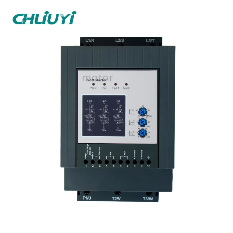
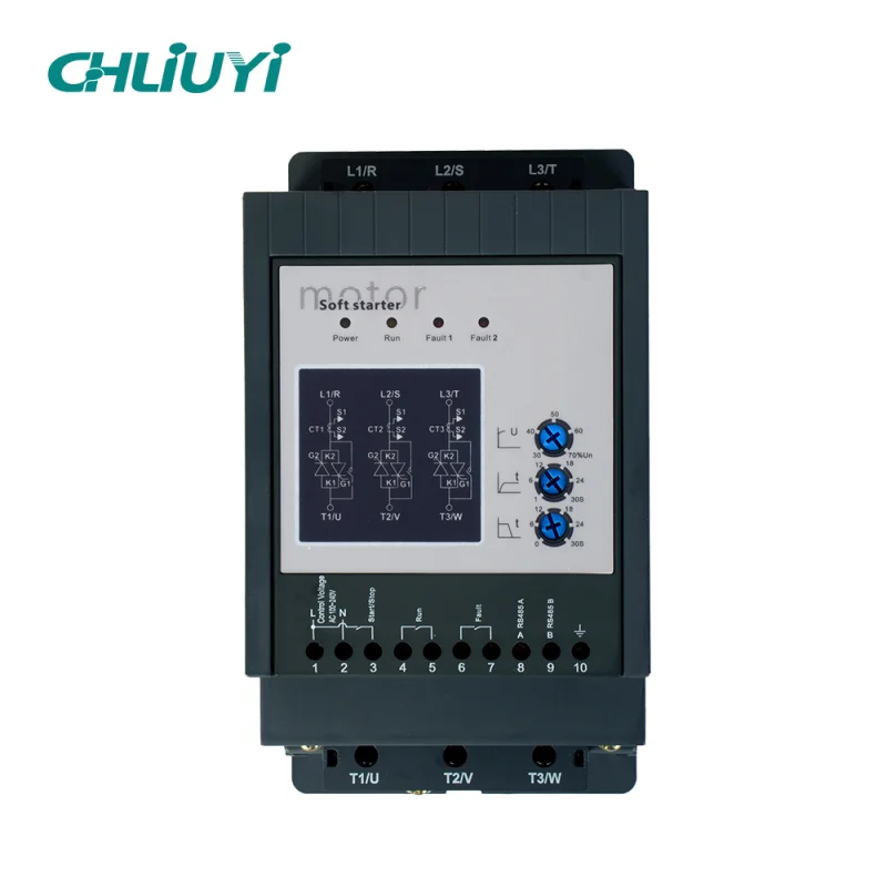
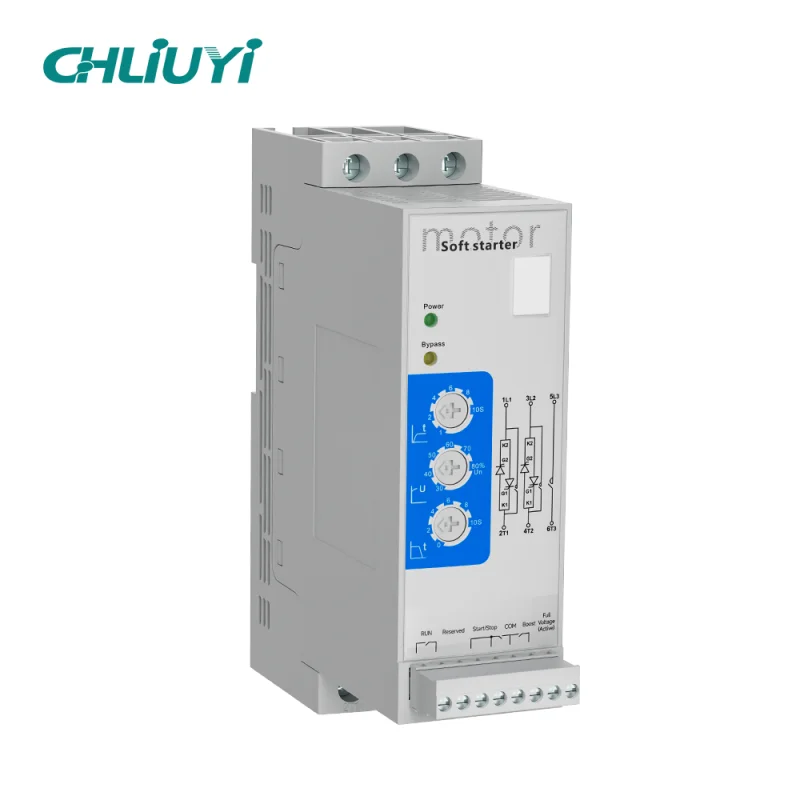
THREE-PHASE ELECTRICITY METER GUIDE RAIL SMART METER
Understanding Three-Phase Rail Smart Meters for Industrial Applications
Three-phase rail smart meters represent specialized electrical measurement devices engineered for industrial power distribution systems utilizing three-phase alternating current. Unlike residential single-phase metering, industrial applications demand simultaneous monitoring of three independent voltage phases—typically designated L1, L2, and L3—along with neutral conductors in four-wire configurations or delta-connected three-wire systems.
Three-Phase Power Distribution Fundamentals
Three-phase electrical systems deliver power through three alternating current waveforms offset by 120 degrees, creating constant instantaneous power delivery essential for industrial motor loads, large HVAC equipment, and production machinery. This configuration provides 73% more power capacity than equivalent single-phase systems using conductors of identical gauge, reducing infrastructure costs and voltage drop in distribution networks. Factory installations typically employ 208V, 400V, or 480V three-phase systems depending on regional standards and equipment specifications.
The balanced distribution of electrical load across three phases prevents the neutral conductor overloading common in single-phase systems with high harmonic content. Manufacturing facilities with significant electronic loads, variable frequency drives, or switching power supplies benefit from three-phase distribution’s inherent power quality advantages. However, load imbalances between phases cause circulating currents, increased losses, and potential neutral conductor issues requiring monitoring through multi-function three-phase meters.
Four-wire wye configurations provide access to both line-to-line voltages (phase to phase) and line-to-neutral voltages, enabling mixed single-phase and three-phase loads within the same distribution system. This flexibility proves valuable in factory environments combining heavy three-phase production equipment with single-phase lighting, control systems, and auxiliary loads.
DIN Rail Mounting Advantages
DIN rail installation standards, specifically the 35mm rail dimension defined in DIN EN 60715, enable tool-free meter mounting through spring-loaded clips or sliding mechanisms. This standardized approach transforms meter installation from complex, time-consuming procedures into simple snap-on operations requiring seconds. The modular nature of DIN rail systems facilitates future expansion, meter replacement, or reconfiguration without disturbing adjacent equipment.
Factory electrical panels utilizing DIN rail mounting accommodate higher device densities compared to traditional individual component mounting methods. Three-phase DIN rail meters typically occupy 4-8 modular units (approximately 72-144mm width), enabling multiple metering points within standard 600mm panel widths. This space efficiency proves critical in retrofit applications where panel space limitations constrain monitoring system expansion.
The mechanical robustness of DIN rail mounting withstands industrial vibration environments where traditional screw-mounted devices experience connection loosening over time. Metal rail construction provides effective grounding paths and mechanical stability under temperature cycling. Professional-grade meters incorporate anti-vibration locking mechanisms preventing accidental disconnection during panel access or nearby equipment operation.
Smart Meter Capabilities and Features
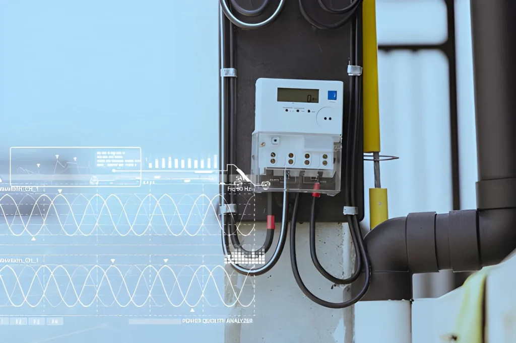
Modern three-phase rail smart meters integrate sophisticated measurement circuits capturing comprehensive power parameters beyond basic energy accumulation. Key monitored parameters include individual phase voltages, phase currents, active power per phase and total, reactive power, apparent power, power factor by phase, frequency, and total harmonic distortion. This multi-dimensional visibility enables facilities engineers to diagnose power quality issues, identify inefficient equipment, and optimize electrical system performance.
Communication capabilities distinguish smart meters from conventional accumulation-only devices. RS485 interfaces implementing Modbus RTU protocol provide standardized connectivity to supervisory control systems, building management platforms, and energy management software. Advanced models incorporate Ethernet connectivity enabling direct integration with IT networks without protocol converters. Wireless options including WiFi and cellular modems suit applications where wired communication proves impractical due to distance or installation constraints.
Data logging functions maintain interval consumption records at 15-minute or hourly resolution, supporting utility demand response programs, time-of-use billing verification, and consumption trend analysis. Internal memory buffers preserve measurement data during communication outages, uploading accumulated records upon connection restoration. This assured data integrity proves essential for regulatory reporting, ISO 50001 energy management compliance, and financial cost allocation systems.
Pre-Installation Planning and Site Assessment
Successful three-phase rail smart meter deployment begins with comprehensive planning addressing electrical system characteristics, physical installation constraints, safety protocols, and integration requirements. Systematic pre-installation assessment prevents commissioning delays, identifies necessary infrastructure upgrades, and ensures regulatory compliance.
Electrical System Documentation and Load Analysis
Initial planning requires detailed documentation of existing electrical distribution infrastructure including one-line diagrams, panel schedules, voltage levels, and maximum load currents. Single-line diagrams illustrate power flow from utility service entrance through transformers, switchgear, and distribution panels to end-use equipment. These drawings identify appropriate metering points providing visibility into critical loads, production areas, or facility subsections requiring independent monitoring.
Load analysis determines meter current ratings ensuring adequate capacity with appropriate safety margins. Maximum expected current should not exceed 80% of meter rated capacity under continuous operation, providing reserve for transient overloads and future load growth. For example, circuits with 60A maximum loading require meters rated 75A or higher—typically selecting 100A models offering substantial margin. Four-pole three-phase meters accommodate neutral current monitoring essential for identifying load imbalances and harmonic issues.
Voltage system configuration—whether three-wire delta or four-wire wye—determines appropriate meter selection and connection methodology. Delta systems lack neutral conductors, requiring three-element metering measuring line-to-line voltages. Wye systems with accessible neutrals enable four-wire metering capturing both line-to-line and line-to-neutral voltages, providing comprehensive visibility into system conditions.
Panel Space Assessment and Layout Planning
Physical site surveys evaluate available panel space, DIN rail capacity, and clearance requirements for meter installation. Standard 35mm DIN rails typically mount horizontally within panel enclosures, with vertical spacing determined by wire bending radius requirements and heat dissipation needs. Manufacturers specify minimum clearances between meters and adjacent devices ensuring adequate ventilation and service access.
Overcrowded panels lacking sufficient space for additional meters require upgrades including larger enclosures, auxiliary panels, or component reorganization. Planning should account for future expansion, reserving DIN rail capacity and panel space for additional monitoring points. Strategic meter placement near monitored circuits minimizes wiring distances reducing installation labor and voltage drop in measurement circuits.
Environmental conditions within panel locations affect meter selection and installation practices. Ambient temperature, humidity, dust, and corrosive atmosphere exposure require consideration. Standard meters specify operating ranges typically spanning -10°C to +55°C ambient temperature. Harsher conditions necessitate meters with extended temperature ratings or protective measures including panel cooling, sealing, or alternative mounting locations.
Regulatory Compliance and Safety Requirements
Electrical installations must comply with applicable codes and standards including National Electrical Code (NEC), IEC electrical installation standards, or regional regulations governing industrial electrical systems. Licensed electricians familiar with local requirements should perform or supervise all installation work, particularly modifications to energized equipment or systems serving critical loads.
Workplace safety protocols require lockout/tagout procedures before accessing energized equipment. Installation planning should identify safe de-energization procedures, equipment requiring backup power maintenance, and production coordination minimizing facility disruption. Some installations proceed under energized conditions utilizing qualified personnel and specialized personal protective equipment (PPE), though this approach increases risk and requires stringent safety protocols.
Utility notification may prove necessary before installing metering affecting utility-owned equipment, service entrance gear, or revenue metering infrastructure. Some jurisdictions require inspection and approval before energizing modified electrical installations. Early coordination with authorities having jurisdiction prevents project delays and ensures compliant installations.
Step-by-Step Installation Procedures
Professional three-phase rail smart meter installation follows systematic procedures ensuring electrical safety, measurement accuracy, and long-term reliability. The following step-by-step process addresses typical factory installations, though specific requirements vary based on facility conditions and equipment specifications.
Safety Preparation and Equipment De-energization
Installation begins with comprehensive lockout/tagout procedures isolating electrical equipment from energy sources. Qualified personnel verify circuits are de-energized using appropriate test equipment measuring phase-to-phase, phase-to-neutral, and phase-to-ground voltages. Never assume circuit breakers in “off” positions ensure safe conditions—always verify absence of voltage before proceeding.
Lockout devices physically prevent circuit breaker or disconnect reclosure during installation. Each person working on equipment applies individual locks ensuring equipment remains isolated until all personnel complete work and remove locks. Tags document lock application date, responsible personnel, and work scope, providing information to facility operators about ongoing electrical work.
Personal protective equipment appropriate for electrical work includes insulated tools, voltage-rated gloves, safety glasses, and flame-resistant clothing. Even with circuits de-energized, PPE provides protection against unexpected energization or induced voltages in adjacent circuits. Arc flash hazard analysis determines appropriate PPE levels for specific work locations and equipment ratings.
DIN Rail Mounting and Mechanical Installation
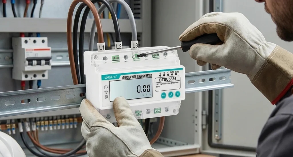
With circuits safely de-energized, installation proceeds to physical meter mounting on DIN rail. Standard 35mm rails feature trapezoidal cross-sections with top hooks and bottom clips securing devices. Most meters mount by hooking the top edge onto the upper rail lip, then pressing the bottom edge down until retention clips engage with an audible click.
Verify secure mounting by gently pulling meters perpendicular to rails—properly installed devices should not release without actuating retention clip release mechanisms. Some meter designs incorporate screw-tightened rail clamps providing positive locking for high-vibration environments. Consult manufacturer instructions for specific mounting procedures as designs vary between products.
Position meters considering cable routing requirements, display visibility, and service access. Maintain specified clearances between meters and adjacent devices per manufacturer recommendations, typically 10-20mm minimum horizontal spacing. Allow adequate clearance above terminal blocks for wire bending radius—at least 6 times cable diameter for rigid cables, less for flexible wire.
Label meters according to facility documentation standards identifying monitored circuits, panel locations, or equipment served. Durable labels withstanding industrial environments use engraved plastic, metal tags, or professional thermal transfer printing. Clear identification proves invaluable during troubleshooting, maintenance, and system expansion activities.
Terminal Block Preparation and Wire Sizing
Before connecting wires, verify meter terminal specifications including wire size acceptance range, terminal screw torque specifications, and conductor material requirements (copper versus aluminum). Most three-phase DIN rail meters accept wire sizes from 1.5mm² to 10mm² (16 AWG to 8 AWG), adequate for direct-connection applications up to 100A.
Calculate appropriate wire sizes based on monitored circuit current ratings and distance from metering points to measurement circuits. Voltage drop in measurement circuits should remain below 0.5% at maximum load to prevent measurement errors. For current-transformer (CT) operated meters, secondary wiring typically employs 2.5mm² minimum conductor size regardless of actual current magnitude due to burden requirements.
Strip wire insulation to lengths matching terminal block depth specifications, typically 8-12mm for cage-clamp terminals or screw terminals. Excessive exposed conductor creates shock hazards and potential short circuit risks. Insufficient insertion depth prevents secure connections increasing resistance and potential overheating. Use wire strippers calibrated for specific conductor sizes ensuring clean cuts without conductor damage.
Ferrules crimp onto stranded wire ends providing solid termination surfaces improving connection reliability and preventing strand damage during screw tightening. European installations commonly mandate ferrules for stranded conductors in screw terminals, though North American practices vary. Ferrule selection should match conductor size with appropriate color coding indicating wire gauge.
Physical Wiring Connections
Wiring sequences for three-phase meters follow standardized patterns, though specific terminal layouts vary by manufacturer. Consult meter-specific connection diagrams during installation, noting differences between three-wire and four-wire configurations. Typical four-wire meter terminal arrangements include:
Voltage Connections:
L1 (Phase A) voltage input
L2 (Phase B) voltage input
L3 (Phase C) voltage input
N (Neutral) voltage reference
Current Connections (Direct or CT Secondary):
L1-IN (Phase A current input)
L1-OUT (Phase A current output)
L2-IN (Phase B current input)
L2-OUT (Phase B current output)
L3-IN (Phase C current input)
L3-OUT (Phase C current output)
Direct-connection meters install in series with monitored circuits, with load current flowing through meter internal current sensors. Connect incoming supply conductors to meter “-IN” terminals and outgoing load conductors to corresponding “-OUT” terminals. Verify correct phase sequence ensuring each voltage input matches its corresponding current measurement path.
CT-operated meters for currents exceeding direct-connection ratings require external current transformers with standardized 5A secondary outputs. Connect CT secondary wiring to meter current terminals observing polarity markings—reversed connections produce negative power readings and incorrect energy accumulation. Never open CT secondary circuits while primary circuits remain energized, as this creates dangerous high voltages potentially damaging equipment and personnel.
Electrical Connection and Wiring Best Practices
Professional wiring practices ensure measurement accuracy, long-term reliability, and electrical safety. Attention to connection quality, wire routing, and grounding proves as critical as meter selection for successful installations.
Terminal Tightening and Connection Verification
Proper terminal screw torque prevents both loose connections causing high resistance and over-tightening damaging conductors or terminals. Manufacturers specify torque values for terminal screws, typically 0.5-0.8 Nm for smaller meters and 1.2-2.5 Nm for higher-current devices. Torque screwdrivers or torque-limiting drivers ensure consistent, appropriate tightening force.
After initial tightening, verify secure connections by gently tugging wires—properly terminated conductors should not pull free from terminals. Visual inspection confirms full conductor insertion into terminal blocks with no exposed bare wire visible outside terminal housings. Multi-strand conductors should show no individual strand damage or fraying from screw compression.
Vibration and thermal cycling cause connection loosening over time, particularly in high-current circuits experiencing significant temperature rise. Re-torque terminal connections 24-48 hours after initial energization, after conductors settle and initial thermal expansion occurs. Document re-torquing in installation records establishing baseline for future maintenance inspection intervals.
Phase Sequence Verification and Correction
Correct phase sequence—the order in which voltage phases reach their peak values—proves critical for accurate power measurement and proper motor rotation direction. Standard phase sequence L1-L2-L3 corresponds to forward rotation; reversed sequences produce incorrect power readings and equipment operational issues. Phase sequence indicators or meters with built-in phase verification features identify proper connections before final energization.
Incorrect phase connections manifest as negative power factor readings, reverse energy accumulation, or anomalous reactive power values. Some meters display phase sequence warnings or error codes during commissioning if voltage and current phase relationships appear improper. Swap phase connections systematically if sequence errors occur, re-verifying after each correction attempt.
Three-phase systems require balanced loading for optimal efficiency and equipment lifespan. Measurement data from newly installed meters enables baseline load balance assessment identifying phases requiring load redistribution. Imbalances exceeding 10% between phase currents suggest opportunities for circuit reassignment improving system performance.
Grounding and Electrical Safety Measures
Proper equipment grounding protects personnel from shock hazards and ensures reliable meter operation. Three-phase DIN rail meters typically incorporate dedicated grounding terminals connecting to panel ground bars or DIN rail ground connections. Verify continuity between meter grounding points and facility grounding electrodes using low-resistance ohmmeters.
Grounding conductor sizing follows electrical code requirements, typically matching circuit conductor size up to certain thresholds. Minimum grounding conductor sizes prevent conductor damage under fault conditions when significant current flows through grounding systems. Color-coded green or green-yellow conductors identify grounding connections preventing inadvertent use for other purposes.
Additional safety measures include clear labeling of panel modifications, updating electrical drawings to reflect new metering installations, and providing operations personnel with meter operation training. Digital display meters with intuitive interfaces simplify ongoing monitoring, though formal training ensures staff understand alarming functions, data interpretation, and appropriate response to abnormal conditions.
Commissioning and System Integration
Following physical installation and wiring completion, systematic commissioning procedures verify proper meter operation, measurement accuracy, and successful integration with monitoring systems. Thorough commissioning prevents operational problems and establishes performance baselines.
Initial Power-Up and Display Verification
Commissioning begins with careful circuit energization following documented re-energization procedures. Monitor voltage measurements during initial power application confirming expected values appear on meter displays. Typical nominal voltages include 208V line-to-line for 208V systems, 400V for European installations, or 480V for North American industrial facilities. Individual phase voltages should read within ±5% of nominal values.
Current measurements should reflect actual connected loads when circuits energize. Zero or anomalous current readings suggest open connections, incorrect CT polarity, or wiring errors requiring immediate investigation. Verify all three phases display appropriate current values—missing readings on individual phases indicate phase-specific connection problems.
Power readings combine voltage and current measurements, displaying instantaneous active power consumption in kilowatts. Negative power readings indicate incorrect CT orientation or phase sequence errors. Power factor displays should range between 0.80 and 1.00 for typical industrial loads—values outside this range suggest measurement errors or unusual electrical conditions.
Communication System Configuration
Meters incorporating RS485, Ethernet, or wireless communication require network configuration before integration with monitoring platforms. RS485 devices need unique slave addresses within 1-247 range, communication baud rate settings (typically 9600 or 19200 bps), and parity configurations matching master system requirements. Consult meter documentation for parameter adjustment procedures, which may involve front-panel buttons, configuration software, or DIP switch settings.
Modbus register maps document available data points and their register addresses enabling SCADA or energy management system configuration. Key registers typically include voltage measurements (registers 0-5), current values (registers 10-15), active power (registers 20-25), and accumulated energy (registers 100-105). Custom integration software or pre-configured SCADA templates accelerate system deployment.
Ethernet-enabled meters require IP address assignment, subnet mask configuration, gateway settings, and port number specifications. Network security policies may mandate VLAN assignment, MAC address registration, or firewall rule configuration allowing communication while protecting network infrastructure from unauthorized access. Coordinate with IT departments ensuring metering systems align with corporate cybersecurity requirements.
Accuracy Verification and Baseline Establishment
Post-commissioning accuracy verification confirms meter readings align with actual electrical conditions. Comparison testing against calibrated reference instruments establishes confidence in reported data. Portable power analyzers or clamp meters measuring identical circuits simultaneously enable field accuracy assessment without laboratory conditions.
Test procedures should evaluate measurement accuracy at multiple load levels spanning light loads, medium loads, and near-rated capacity. Meters may exhibit different accuracy characteristics across load ranges, performing optimally at higher currents while showing degraded accuracy below 20% rated load. Understanding these characteristics informs data interpretation and establishes appropriate applications for specific meter models.
Document commissioning results including verified phase sequences, measured voltages and currents, communication system functionality, and any configuration parameters. This commissioning documentation provides reference information for troubleshooting future operational issues and establishes baseline conditions for ongoing performance monitoring.
Maintenance and Troubleshooting Guidelines
Three-phase rail smart meters require minimal maintenance under normal operating conditions, though periodic inspection, testing, and performance verification ensure continued accuracy and reliability throughout operational lifespans.
Preventive Maintenance Schedules
Establish preventive maintenance intervals based on manufacturer recommendations, operating environment severity, and criticality of monitored circuits. Typical inspection frequencies range from annual reviews for standard environments to quarterly assessments for harsh conditions or mission-critical applications. Preventive maintenance activities include:
Visual Inspection: Examine meters for physical damage, loose mounting, display anomalies, or signs of overheating including discoloration or deformed plastic housings. Check terminal blocks for corrosion, conductor looseness, or insulation damage. Verify wire routing remains secure without chafing against sharp edges or interference with panel access.
Connection Integrity Testing: Re-torque terminal screws to specified values confirming secure electrical connections. Thermal imaging during facility operation reveals elevated temperatures indicating high-resistance connections requiring attention. Temperature differentials exceeding 10°C compared to adjacent similar connections suggest problems.
Communication System Verification: Confirm ongoing data upload to monitoring platforms without gaps or communication errors. Review system logs identifying intermittent connection issues, data quality problems, or cybersecurity concerns. Test remote control functions if applicable, verifying relay operation and fail-safe behaviors.
Accuracy Verification: Periodic comparison testing against calibrated reference instruments validates continued measurement accuracy. Facilities with formal quality management systems may require annual calibration verification maintaining traceability to national metrology standards. Significant deviations from expected values suggest meter degradation requiring replacement.
Common Issues and Diagnostic Approaches
Despite robust engineering, three-phase rail smart meters occasionally experience operational problems requiring systematic diagnosis and resolution. Common failure modes include:
Missing or Incorrect Phase Readings: Individual phase voltage or current measurements reading zero or anomalous values suggest loose connections, blown fuses (if equipped), or internal failure. Verify terminal connections, measure voltages at meter terminals confirming supply presence, and inspect for visible damage. Intermittent readings indicate vibration-induced connection loosening requiring re-tightening and potentially anti-vibration mounting enhancements.
Communication Failures: Loss of data upload to monitoring systems results from network issues, configuration errors, or meter communication hardware faults. Verify network connectivity using standard IT diagnostic tools, confirm communication parameter settings match system requirements, and check for error messages in meter displays. RS485 systems experiencing widespread communication loss often suffer from termination resistor problems, excessive cable length, or electrical noise interference.
Inaccurate Measurements: Readings consistently deviating from expected values may result from incorrect CT ratios, improper voltage connections, or meter calibration drift. Verify CT ratio configuration matches installed transformer ratios, confirm voltage connection points match expected system voltages, and perform reference meter comparison testing. Severe accuracy degradation beyond adjustment capabilities necessitates meter replacement.
Display Malfunctions: Blank displays, incomplete character rendering, or unresponsive controls suggest power supply issues, display hardware failure, or software corruption. Verify meter power supply voltage at terminals, attempt configuration resets per manufacturer instructions, and consider firmware updates if available. Non-functional displays don’t necessarily indicate measurement problems—verify data upload to monitoring systems continues normally.
Long-Term Performance Optimization
Maximize metering system value through ongoing data analysis, system expansion, and capability enhancement. Review consumption trends identifying opportunities for efficiency improvements, load scheduling optimization, and demand management. Anomalous patterns in power factor, harmonic distortion, or phase imbalance suggest equipment problems requiring investigation even if within acceptable operating ranges.
System expansion adding meters to previously unmonitored circuits enhances visibility into facility energy consumption. Prioritize expansion targeting high-energy processes, variable-use equipment, or areas lacking consumption data. Miniature three-phase meters enable economical monitoring expansion when panel space limitations constrain standard meter deployment.
Integration with broader facility management systems including computerized maintenance management systems (CMMS), building automation, or enterprise resource planning (ERP) platforms amplifies metering data value. Energy consumption correlation with production output enables unit energy intensity calculations, benchmarking, and performance tracking against corporate sustainability goals.
Why Professional Manufacturer Selection Matters
Sourcing three-phase rail smart meters from established manufacturers with demonstrated expertise in industrial metering applications provides strategic advantages ensuring long-term system success. Professional manufacturers invest extensively in research and development, quality assurance, and customer support infrastructure unavailable from commodity suppliers.
Manufacturing quality control directly determines measurement accuracy retention, hardware durability, and safety compliance throughout product lifecycles. Leading manufacturers employ precision calibration laboratories maintaining traceability to national metrology institutes, ensuring factory calibrations meet specified accuracy across full operating ranges and environmental conditions. Comprehensive type testing validates performance under electrical transients, temperature extremes, vibration, and humidity exposure characteristic of industrial installations.
Certification portfolios distinguish professional manufacturers from commodity suppliers. Relevant certifications include UL recognition for North American markets, CE marking for European compliance, IEC accuracy class verification (Class 0.5, Class 1, etc.), and voluntary performance certifications from independent testing laboratories. These verifications ensure products meet minimum safety requirements and electromagnetic compatibility standards.
Technical support capabilities prove invaluable throughout product lifecycles. Application engineering assistance during specification, installation guidance during commissioning, and troubleshooting support during operation reflect manufacturer commitment to customer success. Comprehensive documentation including detailed user manuals, wiring diagrams, Modbus register maps, and configuration software simplifies integration and maintenance activities.
Product longevity and ongoing support commitments indicate manufacturer reliability. Established product lines with multi-year availability ensure consistent specifications across facility metering systems simplifying standardization and spare parts management. Active firmware update programs addressing discovered bugs, security vulnerabilities, or feature enhancements demonstrate product stewardship beyond initial sale.
FAQ
What is the difference between direct-connection and CT-operated three-phase rail smart meters?
Direct-connection meters measure current by passing load conductors directly through internal current sensors, supporting maximum currents typically up to 100A continuous rating. These meters install in series with monitored circuits, with all load current flowing through meter terminals. CT-operated meters accept low-current inputs from external current transformers (typically 5A or 1A secondaries), enabling measurement of much higher primary currents—from hundreds to thousands of amperes—without physically passing high currents through meter housings. CT-operated designs provide flexibility in current rating selection through appropriate CT ratio choice, simplify meter replacement without load circuit interruption, and reduce installation labor in high-current applications. However, they require separate CT purchase, installation, and maintenance, increasing total system costs. Choose direct-connection meters for circuits below 80A, CT-operated designs for higher currents or applications valuing future flexibility.
Can three-phase rail smart meters be installed in energized panels without power shutdown?
While technically possible under specific circumstances, installing meters in energized panels requires specialized training, appropriate personal protective equipment (PPE), and strict adherence to electrical safety protocols. Hot work on energized equipment presents significant shock and arc flash hazards potentially causing severe injury or death. Only qualified electricians with appropriate training, experience, and employer authorization should perform energized work. Most industrial facilities prohibit energized work except for diagnostic activities, emergency repairs, or situations where de-energization creates greater hazards than energized work. Standard practice involves de-energizing circuits through lockout/tagout procedures before installation. If operational constraints absolutely prevent shutdown, consider alternative approaches including temporary load transfer to backup circuits, phased installation during partial facility shutdowns, or portable metering temporarily satisfying monitoring needs until proper shutdown windows become available.
How do I determine the correct current rating for a three-phase rail smart meter?
Meter current rating selection requires analysis of maximum expected load current including safety margins for overloads and future growth. Start by identifying circuit breaker or fuse ratings protecting monitored circuits—these represent the maximum possible current under fault conditions. However, normal operating currents typically run significantly below breaker ratings. Review circuit loading documentation, historical current data if available, or measure actual operating currents using portable instruments during peak load conditions. Select meter ratings exceeding maximum operating current by 20-30% providing margin for transient overloads without approaching meter thermal limits. For example, circuits with 60A maximum expected current should employ 75A or 100A rated meters. Avoid excessive oversizing (selecting 100A meters for 10A circuits) as measurement accuracy degrades significantly at low percentages of rated current. Most meters perform optimally between 20% and 120% of rated capacity. Consider CT-operated designs if current requirements exceed 100A or future load growth may require rating increases.
What maintenance does a three-phase rail smart meter require?
Three-phase rail smart meters require minimal maintenance under normal operating conditions, primarily consisting of periodic inspection and connection verification. Annual maintenance schedules should include visual inspection for physical damage, overheating signs, or environmental degradation; terminal screw re-torquing to specified values confirming secure electrical connections; communication system testing verifying ongoing data upload; and basic functionality checks confirming reasonable displayed values. More rigorous biennial or triennial maintenance may include accuracy verification testing comparing meter readings against calibrated reference instruments, particularly for meters supporting utility billing or cost allocation requiring higher confidence levels. Harsh operating environments with temperature extremes, high humidity, or significant vibration may warrant semi-annual inspection frequency. Meters showing anomalous behavior, inconsistent readings, or physical degradation require immediate investigation and potential replacement. Unlike older electromechanical meters requiring periodic calibration, modern electronic meters generally maintain factory accuracy throughout operational lifespans of 10-15 years barring component failures or extreme operating conditions.
Can I connect single-phase loads to three-phase rail smart meters?
Yes, three-phase meters can monitor single-phase loads by utilizing one phase measurement channel, though this represents inefficient use of meter capabilities and costs. For example, connecting a single-phase 230V load between L1 and neutral in a three-phase meter measures consumption correctly, while L2 and L3 channels remain unused. This approach proves acceptable when monitoring mixed loads or consolidated single-phase circuits within three-phase distribution panels. However, dedicated single-phase meters typically cost less than three-phase models while offering equivalent functionality for single-phase applications. Facility-wide metering strategies should deploy appropriate meter types matching monitored loads—three-phase meters for three-phase equipment (motors, HVAC, production machinery) and single-phase meters for lighting, receptacle circuits, and single-phase equipment. Mixed installations requiring both single-phase and three-phase monitoring benefit from standardizing on compatible product families sharing communication protocols, configuration software, and mounting dimensions simplifying installation and long-term support.
Smart Energy Meter Overview Discover the Liuyi eSmart Energy Meter — your reliable digital electricity meter designed for modern homes. Stay in control of your energy with: This WiFi smart energy monitor offers a simple way to manage your energy use, making it the perfect energy-saving device for any household. Key Features & Benefits of […]
Smart meters are changing the way we manage and understand energy consumption in homes, factories, and businesses. With rising demand for accurate utility monitoring, “smart meters” and related long-tail keywords like “real-time energy tracking,” “IoT smart water meters,” and “smart meter installation for factories” are becoming highly relevant for SEO and digital marketing. Whether you’re […]
TABLE OF CONTENTS Industrial facilities seeking comprehensive energy monitoring capabilities increasingly rely on integrating RS485 Modbus energy meters into existing control infrastructure. These communication-enabled devices provide real-time power consumption data essential for energy management systems, predictive maintenance protocols, and operational efficiency optimization. Modern RS485 energy meters utilize the industry-standard Modbus RTU protocol over RS485 physical […]
We use cookies to enhance your browsing experience, serve personalised ads or content, and analyse our traffic. By clicking "Accept All", you consent to our use of cookies.