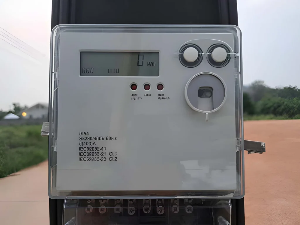
Single Phase Smart Energy Meter: Advanced Hardware Architecture and Metrology Design
The Single Phase Smart Energy Meter represents a sophisticated integration of analog signal conditioning, mixed-signal microcontroller design, and precision metrology algorithms—far beyond simple mechanical metering devices. Rather than presenting only surface-level information, this comprehensive guide explores the architectural foundations, circuit-level implementations, and digital signal processing techniques that enable modern electricity measurement to achieve Class 0.5 or better accuracy across dynamic ranges exceeding 2000:1.
System Architecture Overview
A production-grade Single Phase Smart Energy Meter employs a multi-core or dual-processor architecture to segregate time-critical metrology operations from host application tasks, communications, and user interface functions. The most robust designs utilize a dedicated Analog Front End (AFE) paired with a high-performance microcontroller or microprocessor cluster. For example, Texas Instruments’ MSP430AFE family implements a 24-bit sigma-delta ADC architecture specifically optimized for energy measurement, operating at sampling frequencies around 3.9 kHz to capture 50–60 Hz AC signals with sufficient harmonic content for accurate RMS and power calculations. The metering processor handles foreground and background signal processing in real time, while a separate application processor manages communications protocols (Zigbee, PLC, cellular, or Wi-Fi), remote configuration, and data logging without introducing jitter or measurement latency into the core metrology engine.
This separation of concerns is critical because electricity metering demands microsecond-level timing precision and noise immunity. When the metering core and communication stack run on the same processor sharing memory and I/O bandwidth, context switching and interrupt handling can introduce phase errors and aliasing artifacts that corrupt active and reactive energy calculations. Consequently, modern designs employ isolated inter-processor communication using optical or magnetic isolators on SPI and UART buses, maintaining electrical isolation between the metering section (powered from mains) and the application section (often powered from a separate isolated switched-mode supply). This architecture ensures that transients, switching noise, or software faults in the host processor cannot degrade metrology integrity—a critical requirement for utility-grade meters that must meet IEC 62053 and ANSI C12 accuracy standards.
Analog Front End (AFE) Signal Conditioning
Voltage Measurement Channel
The voltage measurement path in a Single Phase Smart Energy Meter begins with a passive voltage divider using high-precision, low-drift metal-film resistors or thin-film networks to attenuate the mains voltage (typically 110 V or 230 V RMS) down to a safe working level compatible with the microcontroller’s ADC input range. Since many modern metering microcontrollers employ differential sigma-delta converters accepting ±500 mV inputs without level shifting (because they support negative voltages down to –1 V), the design can accept the AC signal directly without DC bias injection. However, to maximize ADC dynamic range and linearity, a DC bias equal to half the supply voltage (typically 1.65 V for 3.3 V logic) is often applied via a precision operational amplifier configured as a summing network.
A low-pass filter comprising a resistor-capacitor (RC) network follows the voltage divider, serving dual purposes: anti-aliasing (preventing frequencies above the Nyquist limit from corrupting the sampled signal) and high-frequency noise attenuation. The anti-aliasing filter cutoff frequency must be carefully chosen—typically 2–3 kHz for 50 Hz mains and 2.5–3.5 kHz for 60 Hz—to attenuate sampling artifacts while preserving the fundamental and harmonic components relevant for accurate power factor and harmonic current measurement. Crucially, different filter time constants are applied to the positive and negative ADC inputs because their input impedances differ significantly; the positive terminal (connected to the high-impedance output of the voltage divider) requires a lower-value resistor to avoid introducing excessive phase shift relative to the current channel.
Component
Function
Specification
Voltage divider resistors
Scale mains (110–230 V) to ADC range (~0–500 mV)
High precision, ±0.1% tolerance, tempco <50 ppm/°C
Anti-alias RC filter
Low-pass filtering at Nyquist frequency
Cutoff ~2–3 kHz (50 Hz) or ~2.5–3.5 kHz (60 Hz)
DC bias network
Shift AC signal around 1.65 V or 2.5 V (half supply)
Precision op-amp (e.g., OPA4376) configured as summing amp
Input protection
Suppress transients and overvoltage
Metal-oxide varistors (MOV) or TVS diodes
Current Measurement Channel
Current measurement in a Single Phase Smart Energy Meter employs either a Current Transformer (CT) or a shunt resistor as the primary transducer, each with distinct trade-offs between isolation, accuracy, and power dissipation. A Current Transformer provides electrical isolation from the mains, protecting the meter circuitry and enabling non-intrusive measurement; however, CTs introduce phase shift (typically 0.1–1° depending on turns ratio and burden), frequency-dependent errors at light loads, and core saturation risks during fault conditions. Shunt resistors offer direct measurement with negligible phase shift and superior linearity but require careful thermal management (especially at high currents) and provide no galvanic isolation.
For the shunt approach, the voltage drop across a precision current-sensing resistor (typically 0.5–2 Ω for residential meters) is amplified through a differential amplifier, usually implemented using a precision op-amp like the OPA4376 or dedicated gain stages. To achieve the target dynamic range of 2000:1 (measuring currents from 0.05 A to 100 A, for example), many designs implement multiple gain stages with different gains that are automatically or manually selected based on the instantaneous current magnitude. A first-stage unity-gain or ×2 amplifier feeds into three or four additional amplification stages with gains of ×6–×330, allowing each stage to optimize for specific current bands while maintaining ±0.5% active power accuracy across the full dynamic range. The AFE or microcontroller firmware includes automatic gain control (AGC) logic that monitors ADC saturation and selects the appropriate gain stage in real time.
Critically, phase compensation is required to correct for the combined phase shift introduced by the CT, shunt amplifier, voltage divider network, and passive filters. Many sigma-delta ADCs offer built-in delay registers (termed PRELOAD or sample delay) that can introduce fractional sample delays with resolution around 0.02° for a 60 Hz fundamental. Phase errors exceeding the built-in compensation range can be corrected in firmware through fractional-delay filtering algorithms, where the software interpolates between past samples to synthesize a 90° phase-shifted voltage signal for reactive power and VAR calculation.
Power Supply Topology for Mains-Powered Meters
A fundamental advantage of Single Phase Smart Energy Meter designs is the ability to derive operational power directly from the AC mains without requiring an external power adapter, reducing bill-of-materials cost and physical footprint. However, this introduces safety and design complexity challenges not present in conventional microcontroller applications.
For low-power designs drawing up to ~25 mA, a capacitive dropper power supply simplifies cost and component count by using a large series capacitor (1–4.7 µF) that exhibits high impedance at mains frequency (50–60 Hz) but passes AC current to a bridge rectifier. The capacitor value is selected using design equations that balance output voltage regulation, inrush current limits, and leakage current safety margins. Following rectification, a small smoothing capacitor (~1–10 µF) and a linear voltage regulator (e.g., LDO) produce a stable 3.3 V or 5 V rail. This topology is extremely cost-effective and suitable for simple single-core meters but suffers from limited current capacity, poor regulation under load variations, and cannot support additional power consumers like RF transceivers.
For designs requiring higher current (e.g., those with wireless communication modules or multiple processor cores), a switched-mode power supply (SMPS) provides isolated 15 V intermediate rails or direct 3.3 V output with significantly better regulation and load capability. A typical topology uses a small flyback or buck-boost converter module powered from the mains through a high-value resistor and bridge rectifier, delivering 10–20 W with isolation ratings exceeding 2 kV for safety compliance. From the 15 V or 24 V intermediate rail, separate LDO regulators provide isolated power to the metering and application sections, ensuring that switching noise from the SMPS does not couple into the analog measurement channels through shared ground return paths.
Sigma-Delta ADC Architecture and Filtering
The heart of modern Single Phase Smart Energy Meter design is the 24-bit sigma-delta (ΣΔ) Analog-to-Digital Converter integrated into the metering microcontroller. Unlike conventional successive-approximation or flash ADCs, sigma-delta converters trade high resolution and noise performance for lower sampling rates and computational complexity. A typical metrology application configures the ΣΔ with an Oversampling Ratio (OSR) of 256 and a modulation frequency of 1 MHz, yielding an effective sampling frequency around 3.9 kHz—sufficient to capture the fundamental and up to the 13th harmonic of 60 Hz AC signals (780 Hz), or the 15th harmonic at 50 Hz (750 Hz).
The ΣΔ architecture fundamentally differs from direct-conversion ADCs: rather than measuring the instantaneous analog voltage and directly converting to a digital code, the ΣΔ converts the analog input into a high-frequency 1-bit stream through internal feedback loops. This bit stream is then digital-filtered and decimated to extract the final N-bit (e.g., 24-bit) output at a lower rate. The advantages are threefold: (1) intrinsically high linearity with minimal DNL (Differential Non-Linearity) and INL (Integral Non-Linearity) errors compared to multi-bit ADCs, (2) noise shaping that pushes quantization noise to high frequencies (easily filtered out), and (3) excellent rejection of 50/60 Hz mains interference when OSR and modulation frequency are tuned appropriately. A well-designed ΣΔ meter can achieve Effective Number of Bits (ENOB) of 16–18 bits in practice, far exceeding the nominal bit count through noise reduction.
Three independent ΣΔ channels are typically allocated in a single-phase meter: two for current measurement (line and neutral or two tap points for detection of neutral tampering or asymmetry), and one for voltage. Modern AFE designs allow simultaneous sampling of multiple channels on the same trigger pulse, ensuring that voltage and current samples are time-aligned to eliminate cross-coupling errors in power calculations.
Metrology Processing: Foreground and Background
Once raw ADC samples are acquired, they flow through a sophisticated dual-process software framework that separates real-time, deterministic metrology from averaging and calibration adjustments.
The Background Process runs synchronously with each ΣΔ ADC interrupt (occurring ~3,906 times per second at 60 Hz). Its responsibilities include:
DC offset removal via a high-pass filter, tracking and subtracting stray DC bias introduced by analog components or microcontroller ADC offset.
Accumulation of squared voltage and current samples into 48-bit registers for RMS calculation.
Multiplication of instantaneous voltage and current samples to generate instantaneous power (both active and reactive energy through 90° phase-shifted voltage).
Frequency measurement via zero-crossing detection with linear interpolation and low-pass filtering to suppress noise-induced jitter.
Tracking of whether current leads or lags voltage to determine the sign of reactive power and power factor.
Approximately one second’s worth of samples (typically 50–60 cycles synchronized to mains zero-crossings) accumulates, at which point the background process signals the foreground to begin averaging and final calculations.
The Foreground Process executes less frequently (roughly once per second or on demand from the application processor) and performs mathematically intensive operations that define the final metering parameters. Using the accumulated 48-bit registers from the background, it calculates:
RMS Voltage: VRMS=Kv∑n=1Nv(n)2NV_{\text{RMS}} = K_v \sqrt{\frac{\sum_{n=1}^{N} v(n)^2}{N}}VRMS=KvN∑n=1Nv(n)2 where KvK_vKv is a scaling factor and NNN is the sample count over the averaging period.
RMS Current: IRMS=Ki∑n=1Ni(n)2NI_{\text{RMS}} = K_i \sqrt{\frac{\sum_{n=1}^{N} i(n)^2}{N}}IRMS=KiN∑n=1Ni(n)2 with analogous scaling.
Active Power: P=Kp∑n=1Nv(n)⋅i(n)NP = K_p \frac{\sum_{n=1}^{N} v(n) \cdot i(n)}{N}P=KpN∑n=1Nv(n)⋅i(n) representing true power (watts) in phase with the voltage.
Reactive Power (90° shift method): Q=Kq∑n=1Nv90(n)⋅i(n)NQ = K_q \frac{\sum_{n=1}^{N} v_{90}(n) \cdot i(n)}{N}Q=KqN∑n=1Nv90(n)⋅i(n) where v90(n)v_{90}(n)v90(n) is voltage shifted by 90° in software or hardware.
Power Factor: PF=PS\text{PF} = \frac{P}{S}PF=SP with sign indicating leading (capacitive) or lagging (inductive) current.
Frequency: Converted from sample-per-cycle measurements to Hz.
This architectural separation is essential for meter accuracy. By isolating real-time, jitter-sensitive operations (ADC reading, sample accumulation) from complex calculations and external communication, the design ensures that the foreground process never blocks the background ISR, preventing timing uncertainty that would corrupt power calculations.
Active and Reactive Energy Pulse Generation
Energy pulses (often called “kWh pulses” or “imp/kWh”) are generated based on accumulated active and reactive energy, typically at rates specified by meter manufacturers (e.g., 1,600 pulses per kWh). Rather than generating pulses deterministically whenever energy thresholds are crossed—which would introduce timing jitter at low power levels—modern designs use a dithering technique: the average power calculated by the foreground process is accumulated every ΣΔ interrupt, gradually building toward the energy threshold, and a pulse is emitted when the accumulated value exceeds the threshold, with the excess carried forward to the next cycle. This method produces steady, jitter-free pulses even at light loads, enabling accurate calibration and maintaining the integrity of load profiling data used by utilities for demand-side management.
Calibration and Trimming
A production Single Phase Smart Energy Meter undergoes multi-stage calibration to compensate for component tolerances, temperature coefficients, and CT or shunt sensor non-idealities.
The calibration typically follows this sequence: (1) Current gain calibration at each gain stage, comparing measured RMS current against a reference standard to determine individual scaling factors KiK_iKi for each hardware stage. (2) Voltage gain calibration, similarly adjusting KvK_vKv using a precision voltage reference. (3) Active power calibration at unity power factor (0°), ensuring that the product of voltage and current samples correctly yields watts. (4) Phase calibration at 60° or –60° phase angle, using the fractional-delay PRELOAD register or software algorithm to align current and voltage waveforms optimally. (5) Accuracy verification across the full dynamic range and multiple power factors, confirming that active power error remains within ±0.5% or tighter as required by the application.
Calibration constants (gain factors, phase delay, energy pulse thresholds) are typically stored in non-volatile EEPROM accessible to both the metrology engine and the application processor, allowing field recalibration if component aging or environmental factors degrade accuracy over time.
Conclusion and Implementation Considerations
The Single Phase Smart Energy Meter of today is far more than a digital display of kilowatt-hours. Modern designs integrate precision analog signal conditioning, multi-core processors with real-time constraints, sophisticated digital filtering, and calibration frameworks that collectively achieve accuracy and reliability comparable to laboratory instruments. Understanding these architectural and circuit-level details is essential for anyone specifying, designing, or deploying meters in utility or industrial applications.
If you require a custom Single Phase Smart Energy Meter tailored to your voltage and current ranges, communication protocols, accuracy targets, or environmental conditions—or if you need assistance integrating advanced metrology functions such as harmonic analysis, power quality monitoring, or demand-side response—we invite you to share your technical requirements, applicable standards (IEC, ANSI, local regulations), and volume projections. Our team can work with you to select the optimal microcontroller platform, analog front-end architecture, and calibration approach, then provide detailed datasheets, reference schematics, firmware examples, and production test procedures to accelerate your deployment.
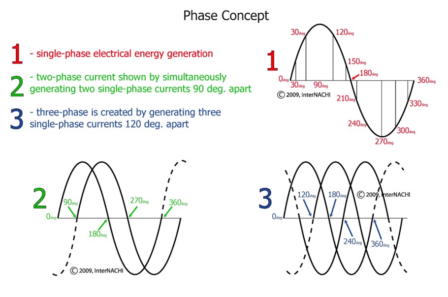
Single phase vs three phase are terms that refer to the distribution of electrical loads. In electricity, a phase defines how power is delivered. Single-phase power consists of two wires in an alternating current (AC) circuit, usually one phase wire and one neutral wire, with current flowing between them through the load. Three-phase power, however, […]
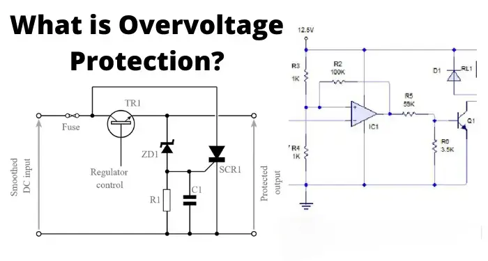
Discover comprehensive overvoltage protection techniques to safeguard your electrical systems. Learn how to prevent damage from lightning, switching, and other surges—keep your power system safe today!
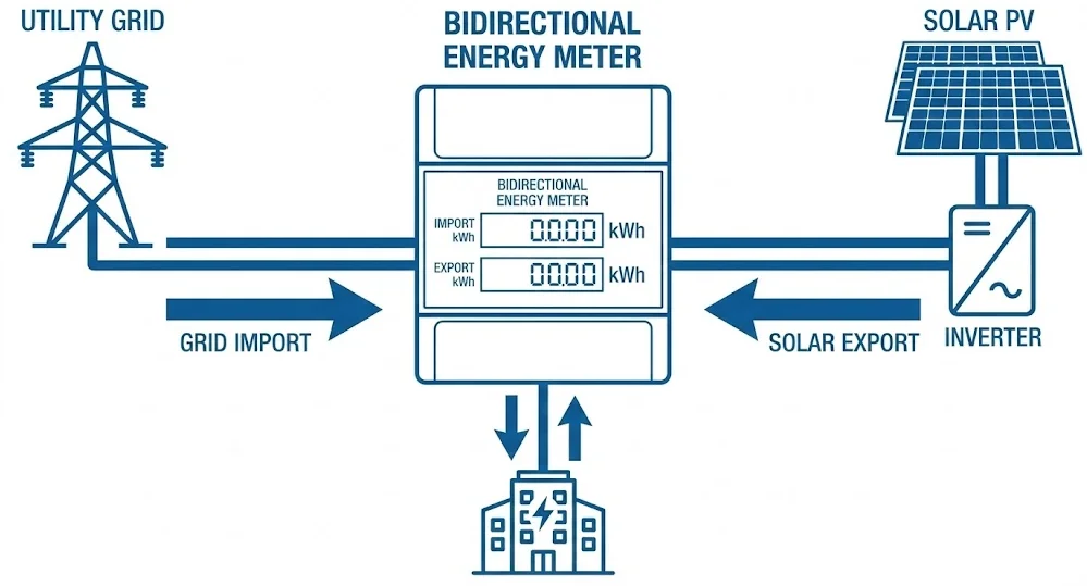
TABLE OF CONTENTS Bidirectional energy metering represents a critical advancement in solar photovoltaic infrastructure, enabling precise measurement of both grid consumption and solar energy export. As industrial facilities and commercial properties increasingly adopt renewable energy solutions, understanding bidirectional energy metering becomes essential for optimizing energy costs and ensuring regulatory compliance. This technology transforms conventional one-way […]
We use cookies to enhance your browsing experience, serve personalised ads or content, and analyse our traffic. By clicking "Accept All", you consent to our use of cookies.